
Index to CNC-related Engineer in Wonderland blogs
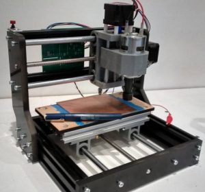
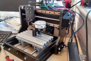
It started life as a ‘1610Pro’ cnc (left), bought to learn about cnc cutting, which revealed its slack and flexibility as soon as it was assembled.
Not that it wasn’t great fun, interesting and educational, it just wasn’t very precise.
The route to improvement was immediately obvious, but it has taken three years to find the spare time to do it.  January 2021 bright idea (right)
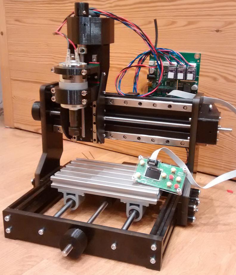
As originally envisaged, improvements (I claim they are improvements 🙂 are built around four linear rails bought cheaply as spares for 3d printers, plus a bunch of 3d prints.
Designing these prints has been a wonderful learning experience, consuming days of lifetime, but only wasting about 1kg of PLA (which in this case was made from waste material).
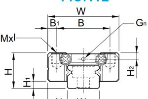
Available linear rails came in fixed lengths, so the mods were built around them, and an aluminium extrusion replaced the twin 10mm round rods that are the weakest (least stiff) link in the original design – heaven knows how floppy the 3018 versions are (scroll down to ‘a note on structural stiffness’ here).
Extra z-height in the new version was mandated by the 150mm long MGN7-style rails, and has a hidden benefit – it can now hold quite long twist drills for making patterns of holes.
The new version would have more stiffness if the anti-backlash nuts were brass rather than printed PLA, but the plastic ones are better than the original brass-plus-springs concept, and the 6mm thick printed z-axis carrier has been designed to be replaced with a 6mm aluminium plate if need-be, but the 3mm thick printed side plate that turn it into an H-beam seem to be doing a pretty good job.
 Side view today
Belt drives replace axial connectors between the motor and leadscrews (x-axis just visible left) to allow the leadscrews to have proper thrust bearings while allowing for a little motor-leadscrew misalignment. Belt-drive also allows the spindle motor to be closer to the x-axis as the spindle motor no longer needs to miss the stepper motor.
The whole thing is not quite ‘finished’ as some of the parts need re-printing to correct details, and it would be better with end-stop switches adding to the three axis.
I also have an idea to stiffen and lengthen the Y-axis (front-back movement), but this assembly the best part of the original design, with very little flex or slack (I only replaced the anti-backlash nut assembly) and it would only increase Y-axis travel from 100 t0 150mm.
Excuse the poor photos – which were taken with an old mobile in poor light early this morning.
Congrats on reaching completion of the project, however temporary that may be. 🙂 I hope it provides the capabilities you were looking for, and I look forward to the news of projects that it has made possible. I suppose the inevitable question of whether it was a good use of limited time will be asked, or whether it would have been better to just buy the suitable commercially built CNC… but that ignores the benefit of the learning process and the fun involved. I know that I’m guilty of choosing to build something that could just be purchased, simply because it would be fun to have the experience. Only in retrospect do I learn whether I should have just bought one. Hey, that’s how you learn, right??